power connection:
| mains voltage |
100 – 240 V AC, 50 / 60 Hz, 140 – 340 V DC |
| current consumption |
max. 0.5 A / 230 V AC
max. 0.75 A / 115 V AC |
| connection |
connecting terminal, tool-free with lever, max. 4 mm²
earthing screw M5 |
| level of protection |
IP40 |
| cable entry |
cable gland PG13.5 |
connection emergency light supply:
| input voltage |
22 – 28 V DC |
| current consumption |
max. 1.5 A |
| connection |
screw terminal 2-pole, max. 2.5 mm² |
connection control signal “locking”:
| input voltage |
a) 20 – 60 V AC / DC or
b) 60 – 250 V AC / DC |
| current consumption |
max. 3.5 mA |
| connection |
screw terminal 3-pole, max. 2.5 mm² |
| cable entry |
cable gland PG13.5 |
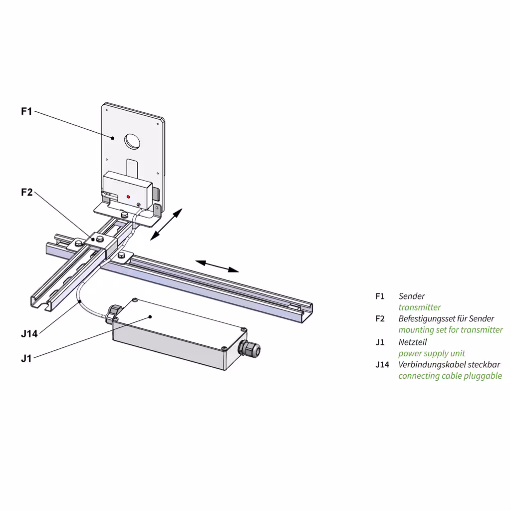
connection transmitter:
| output voltage |
24 V DC |
| cable length |
1 m |
| connection |
plug connector on both sides, 3-pole |
| cable entry |
cable gland M16x1.5 |
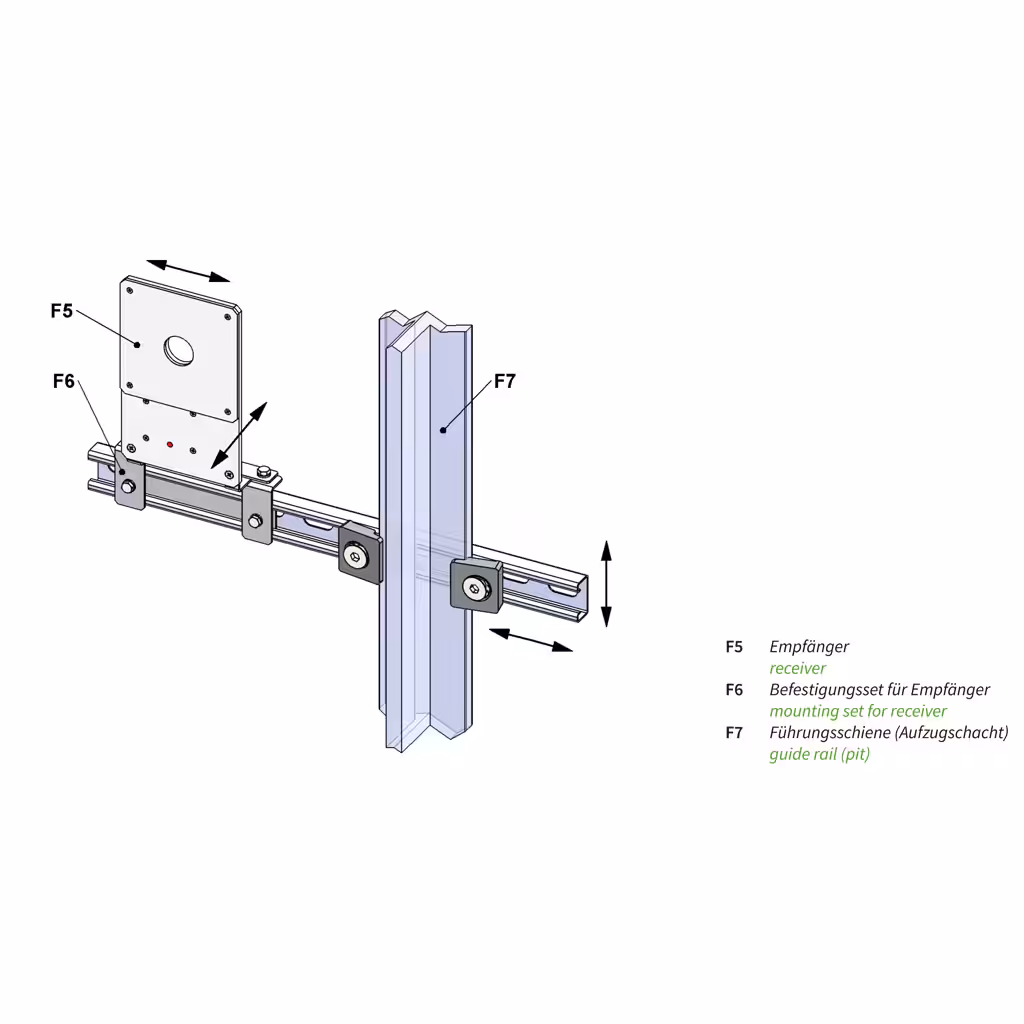
receiver:
| output voltage |
24 V DC, galvanically isolated |
| output current |
1.0 A, max. 30 seconds (10% duty cycle)
0.2 A, for an indefinite period |
| connection |
connecting terminal, tool-free with lever, max. 4 mm² |
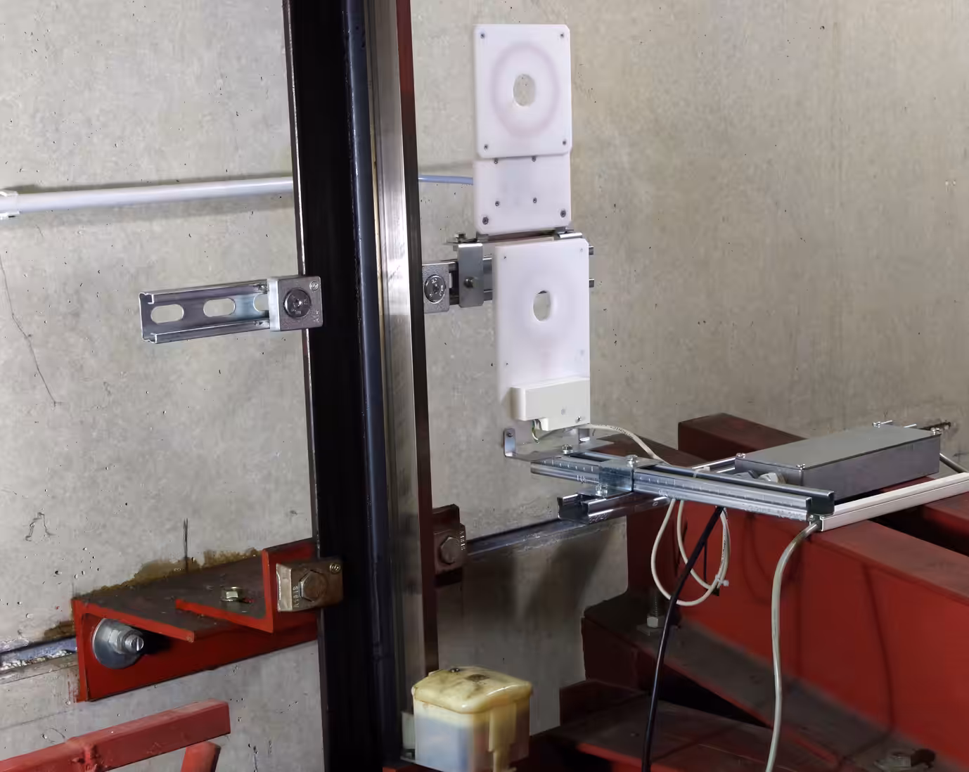
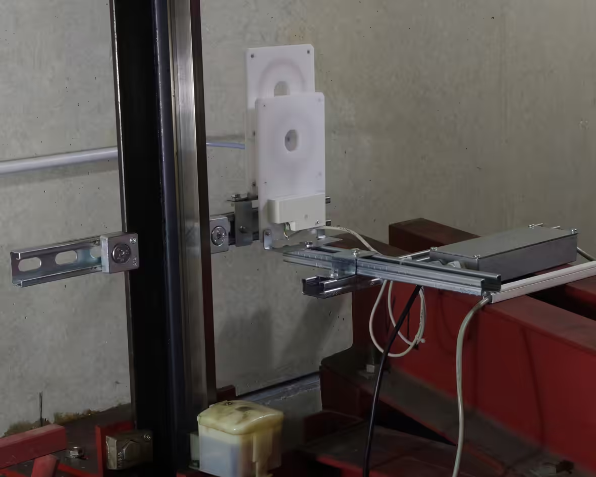
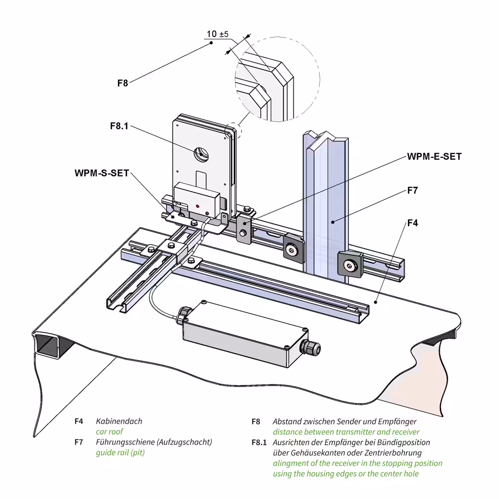
permissible distance and misalignment between transmitter and receiver in the stop:
| distance |
10 mm +/- 5 mm |
| stopping position area |
max. +/- 25 mm (at 10 mm distance) |
| re-levelling range |
max. +/- 40 mm (at 10 mm distance) |
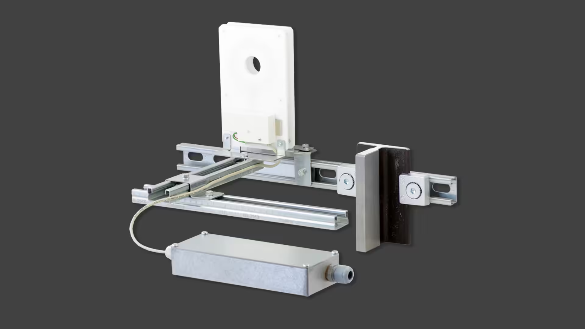
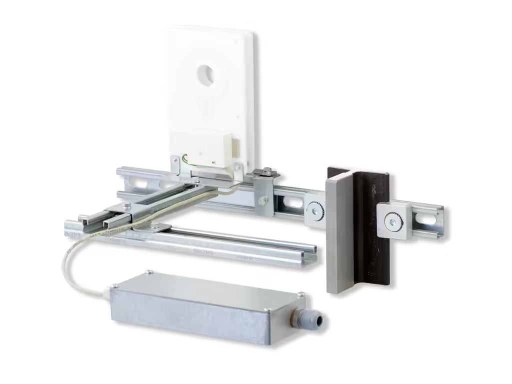
minimum distance from metal surfaces to the transmitter and receiver coil*:
| transmitter |
> 30 mm |
| receiver |
> 50 mm |
weight:
| WPM-S-SET |
2380 g |
| WPM-E-SET |
1520 g |
* Metal parts close to the transmitter and in particular to the receiver coil can significantly disrupt energy transmission.
Therefore place the receiver coil in such a way that the minimum distances to metal surfaces are observed.